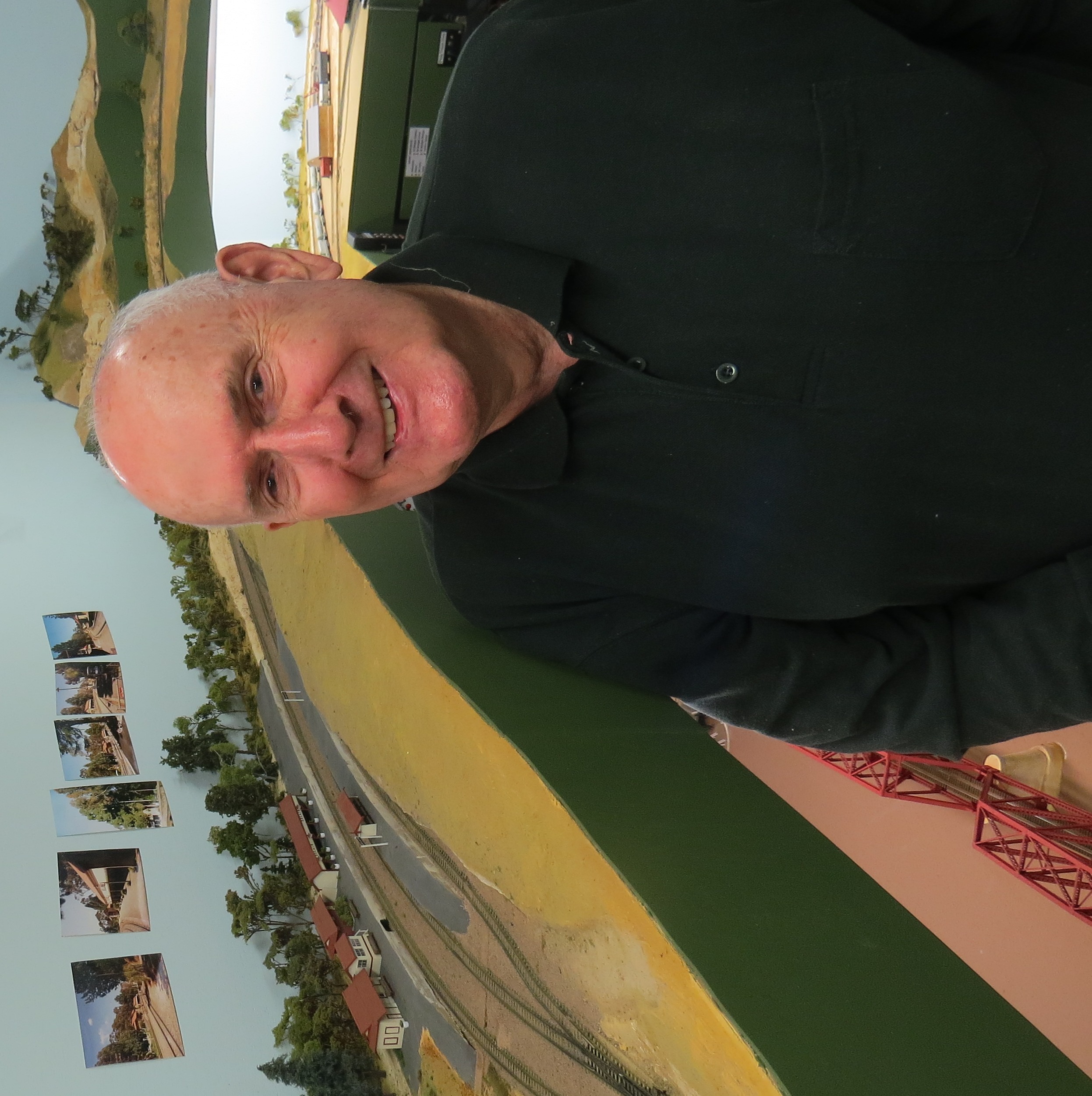
My home layout is based on Belair, the station in the Adelaide Hills where I lived for five years. The layout is called The Belair and Murray Bridge Railway (BAMBRY) because it models the run through the Adelaide hills and on to Murray Bridge and Tailem Bend. Although not originally the intention, the main aim of the layout has become realistic operations of this mainline segment, following as much as possible the SAR and ANR timetables for the appropriate era. The layout attempts to reproduce the line as it existed in the mid-1980s, when I lived there. This allows the through running of VR/V/Line trains, and covers the period of colour scheme transitions from SAR to ANR to AN, and from VR to V/Line, giving plenty of scope for variety.
The layout consists of 3 levels (well, 2½) with open access. The line climbs naturally through the Hills from Adelaide, in the middle, to Belair then Mount Lofty on the top, with the lower level modelling Murray Bridge reached via a helix. A loop around the middle of the helix links to Adelaide for staging.
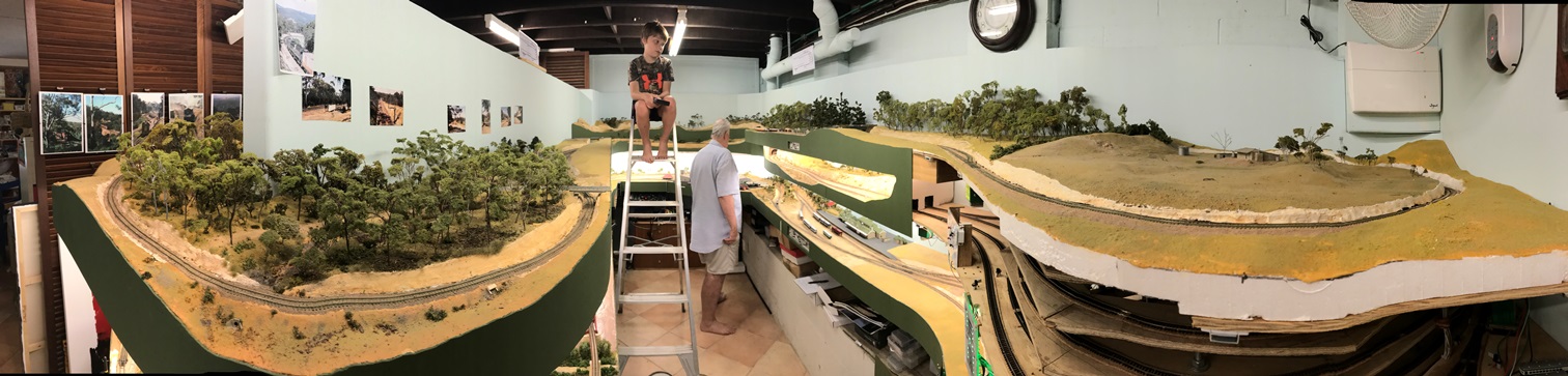
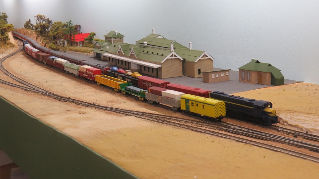
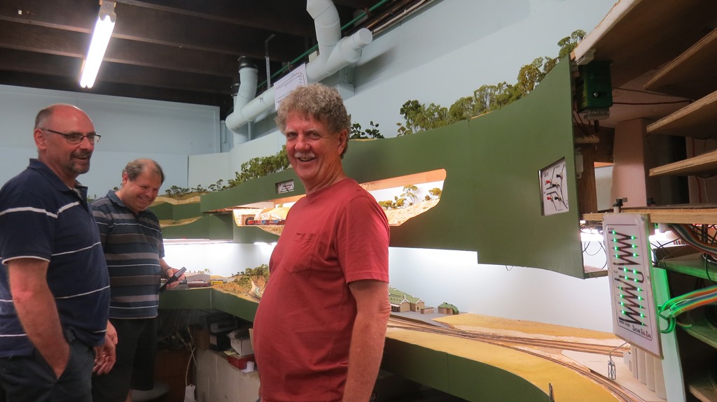
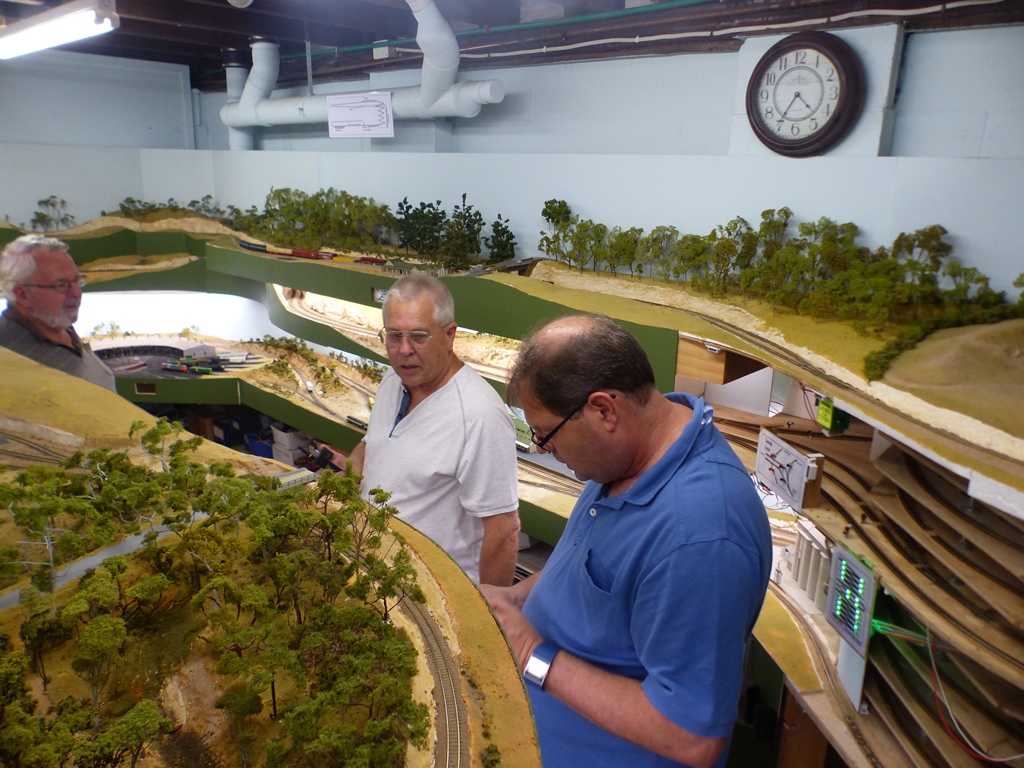
Panoramic view of the whole layout - operation under the watchful supervision of a grandson.
Mt Lofty, at the top of the grade
A freight waits at Murray Bridge for the morning stop of The Overland
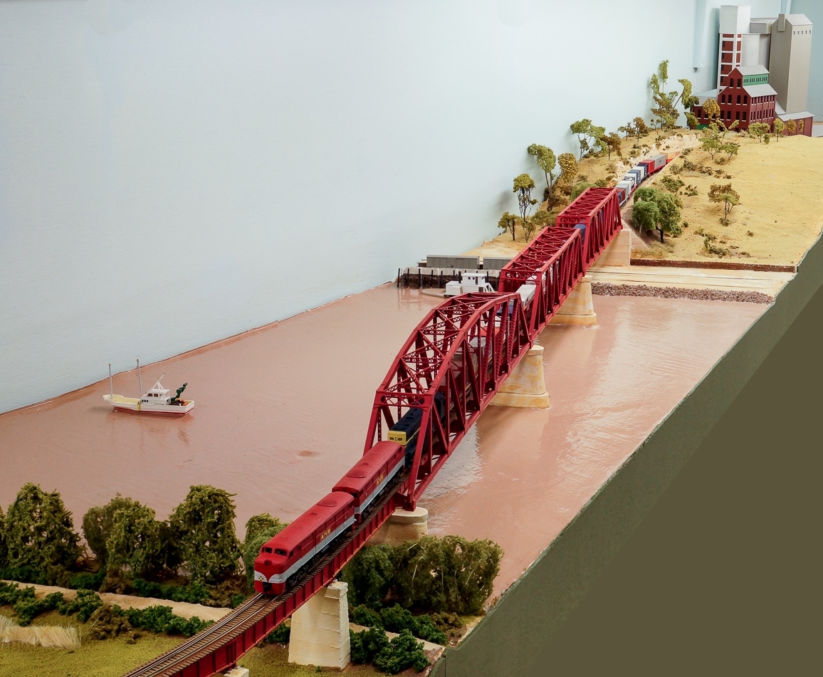
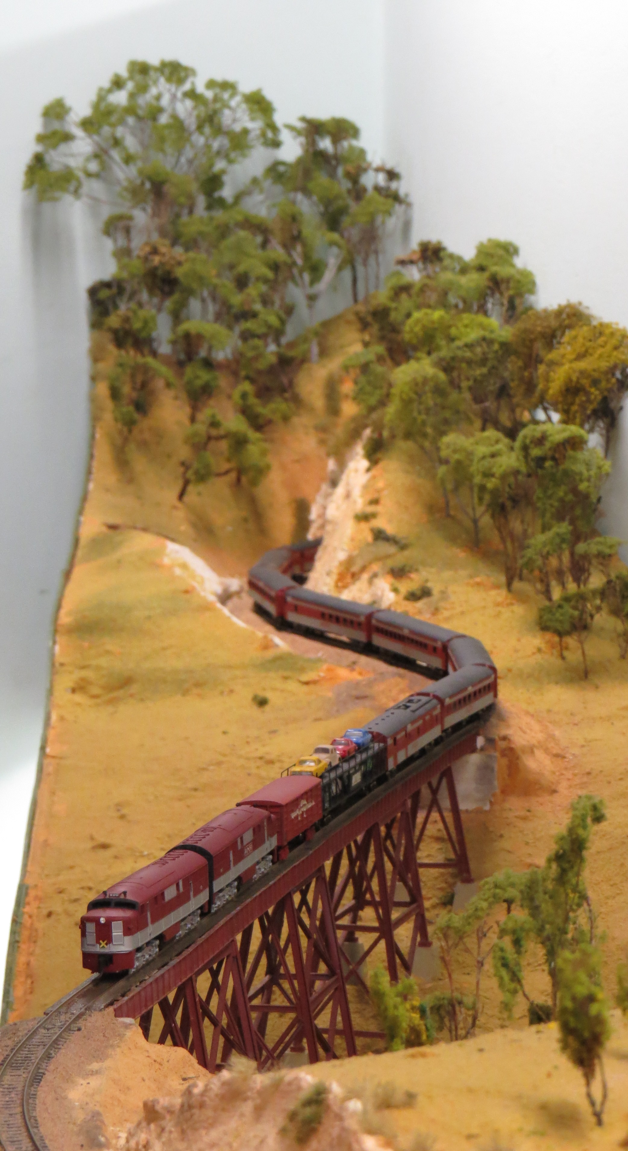
The bridge over the Murray at Murray Bridge
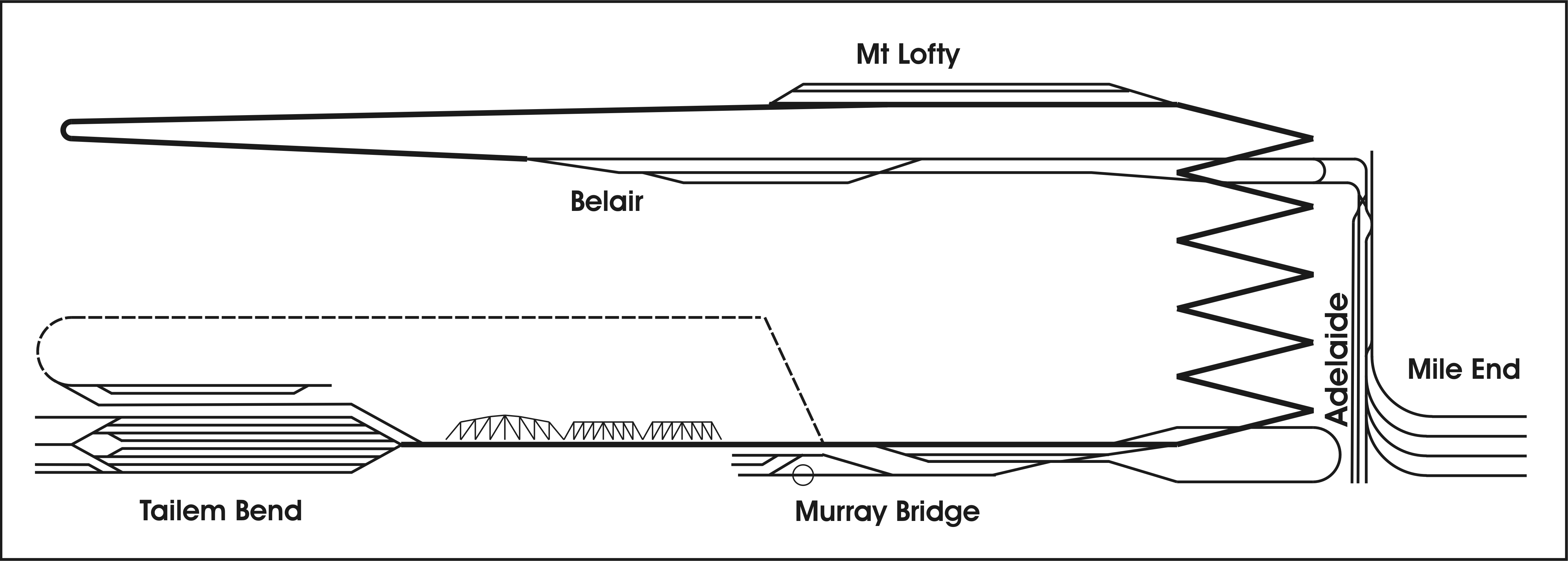
Layout schematic diagram
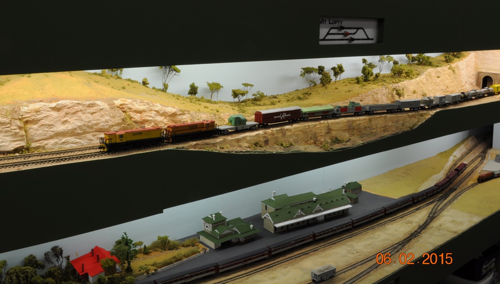
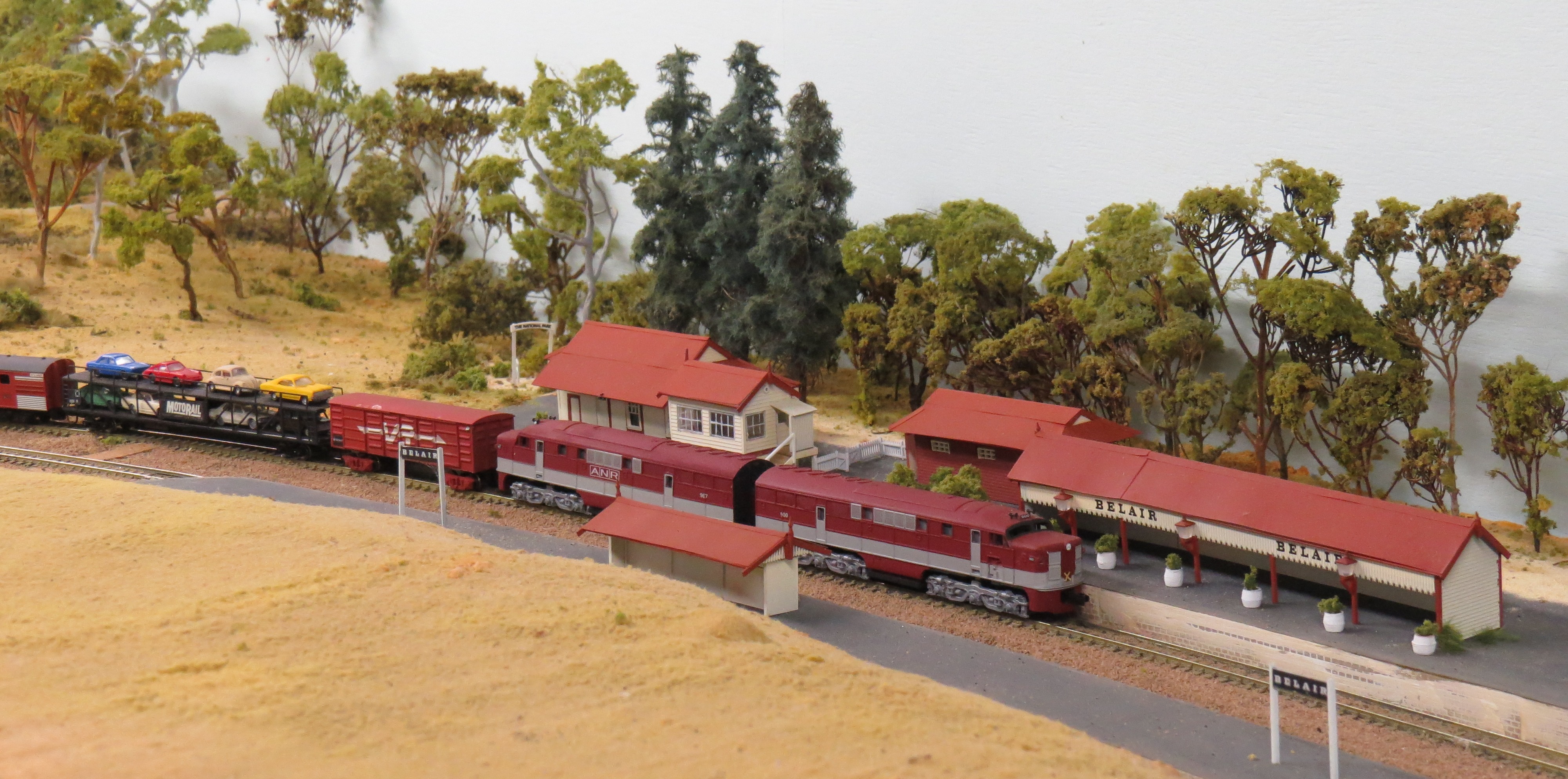
A mixed freight leaves Adelaide for Belair, while The Overland makes its morning stop in Murray Bridge
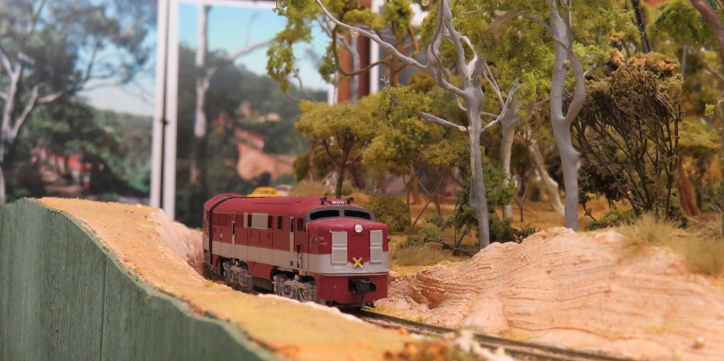
The Overland rounds Foster's Corner near Belair
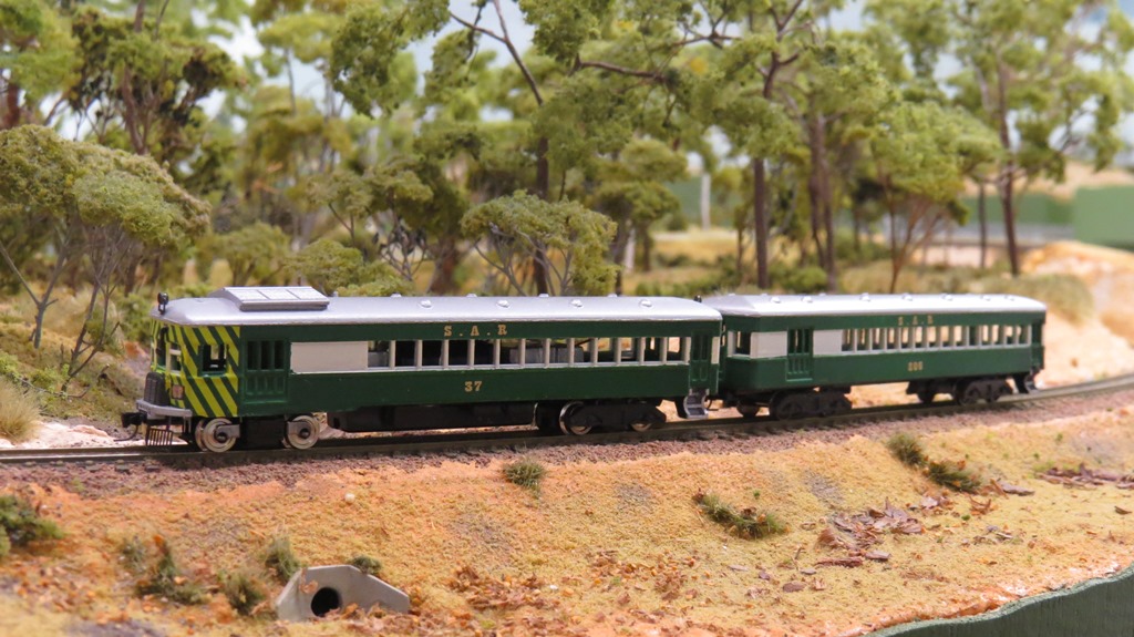
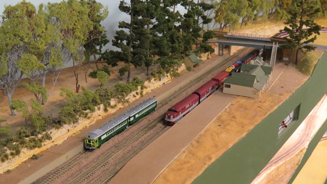
Brill 75 railcar set passes through Belair National Park
The Overland winds down through the Adelaide Hills
The aim during operations is to run trains to the timetable, but also essentially TO HAVE FUN
Signalling on Belair
A long term project was started quite a few years ago to introduce signalling, with block detection, to control the flow of traffic on the single track sections of the layout (which is most of it). Work got seriously underway in 2022 and has lasted well into 2023 and will probably spill into the next year as well. For various reasons it was decided not to use a DCC based system, which would have greatly simplified wiring, but required a decoder for each signal light. Another factor was the need to maintain two separate control panels, one at Adelaide and one at Tailem Bend, to control half the layout each. This was to suit the system of operation which has evolved over the years, whereby the yardmasters at Adelaide and Tailem Bend each control half the layout, from their location to Mt Lofty. We tried working with a full-time controller, but there was insufficient work to justify the position, hence the current system. The electronic system chosen for the signals was Arduino based and because of the complexity has ended up with three separate "brainboxes" each with its own Arduino plus input and output devices. Signals, when they finally arrive, will be built from San Mateo kits of SAR prototype style.
The control panels contain switches to clear paths into stations or into single track sections. They also have indicator lights for the occupancy detectors in each mainline section, plus repeaters of all the signal indications.
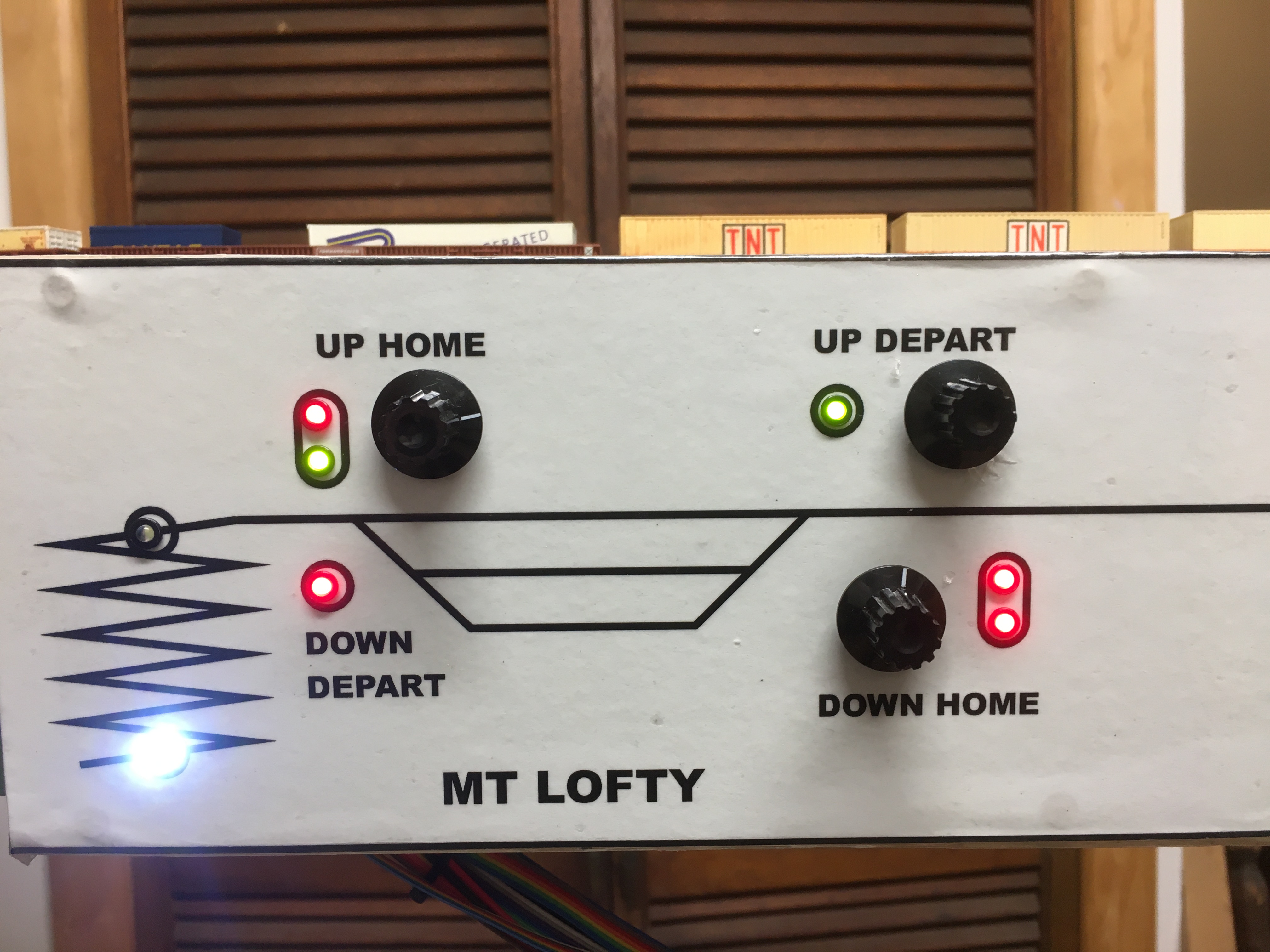
Part of the Adelaide control panel, showing the switches, indicators and signal repeaters for Mt Lofty station
The control panels were also deliberately made of sheet steel, so that magnetic tags can be held in place. Tags were then made to indicate the train number of all trains that are operated on the layout. The controller can then locate a tag to indicate in which section a train has been authorised to operate. This enables the controllers to keep track of the trains under their control. The tags are colour coded according to the type of train - red for passenger, green for express freight, pink for suburban etc.
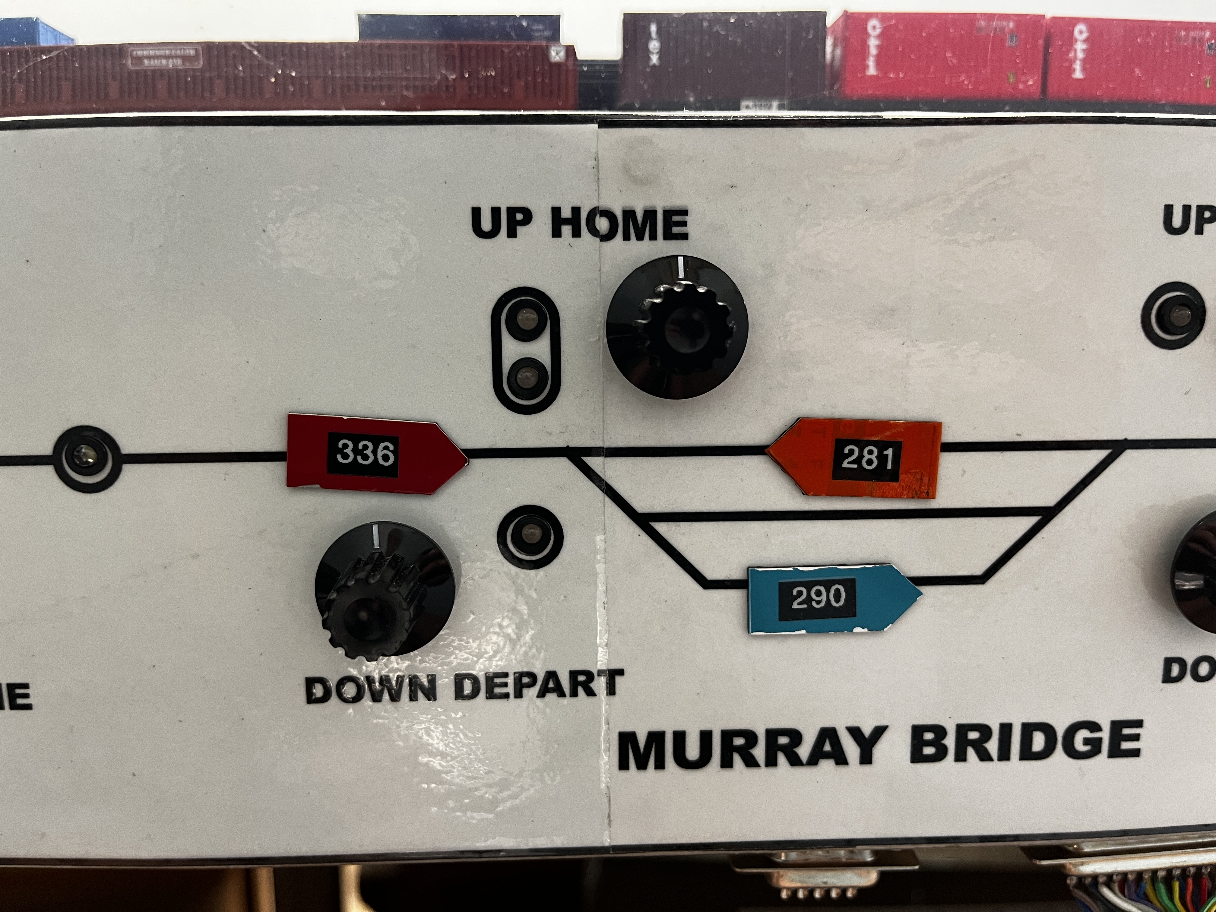
Use of the magnetic tags: a busy moment at Murray Bridge with 281 Mt Gambier Bluebird in the platform, 290 goods working the yard and 336 Tailem Bend Passenger waiting to enter.
The electronics associated with performing the logic of the signalling system is quite complex and has involved making a huge number of terminations. The wiring is also complex, and has involved over a kilometre of single core wire.
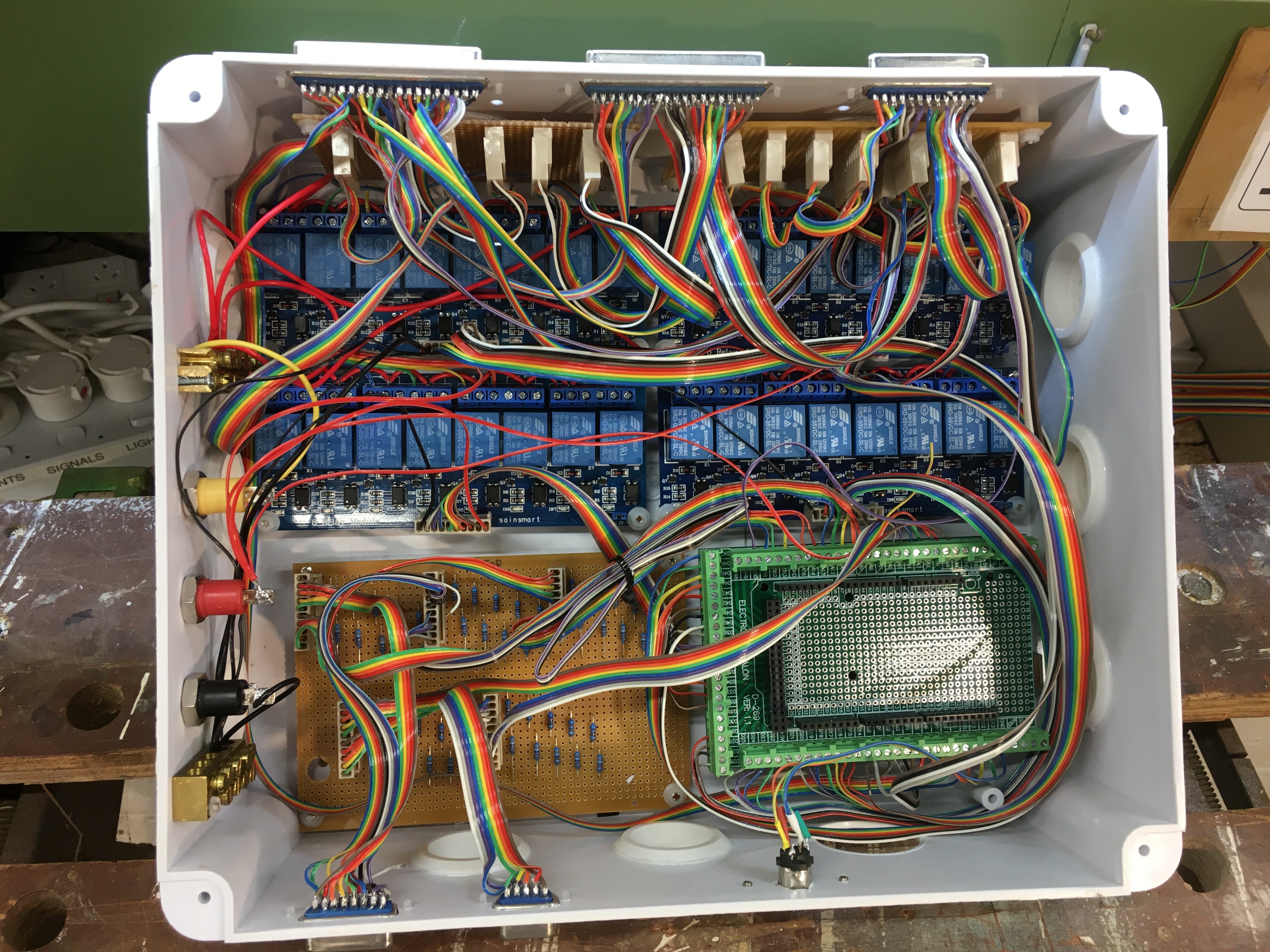
The "brainbox" which controls signals at Mt Lofty and Murray Bridge. Arduino Mega lower right, relays to give 12V output top, circuitry to condition input signals lower left.
The brainboxes control signals in adjacent sections of the layout: one for Mt Lofty and Murray Bridge (which are one above the other); another for Belair and Tailem Bend; and a smaller one for Adelaide. The amount of hardware can be seen in the photo - all that to control four home signals, four starter signals and two signals at the intermediate location Nairne. This block post was introduced roughly halfway through the helix to enable one train to follow another in the same direction, thereby saving waiting time on what is otherwise the longest section of the layout. Nairne is at approximately a proportional distance between Mt Lofty and Murray Bridge in the real world.
While it is the intention to have lineside signals at most locations, some would be located inside the helix, which is usually covered and therefore not visible to drivers. Therefore a small panel of repeaters was provided to show the Nairne signals and the Murray Bridge Down Home.
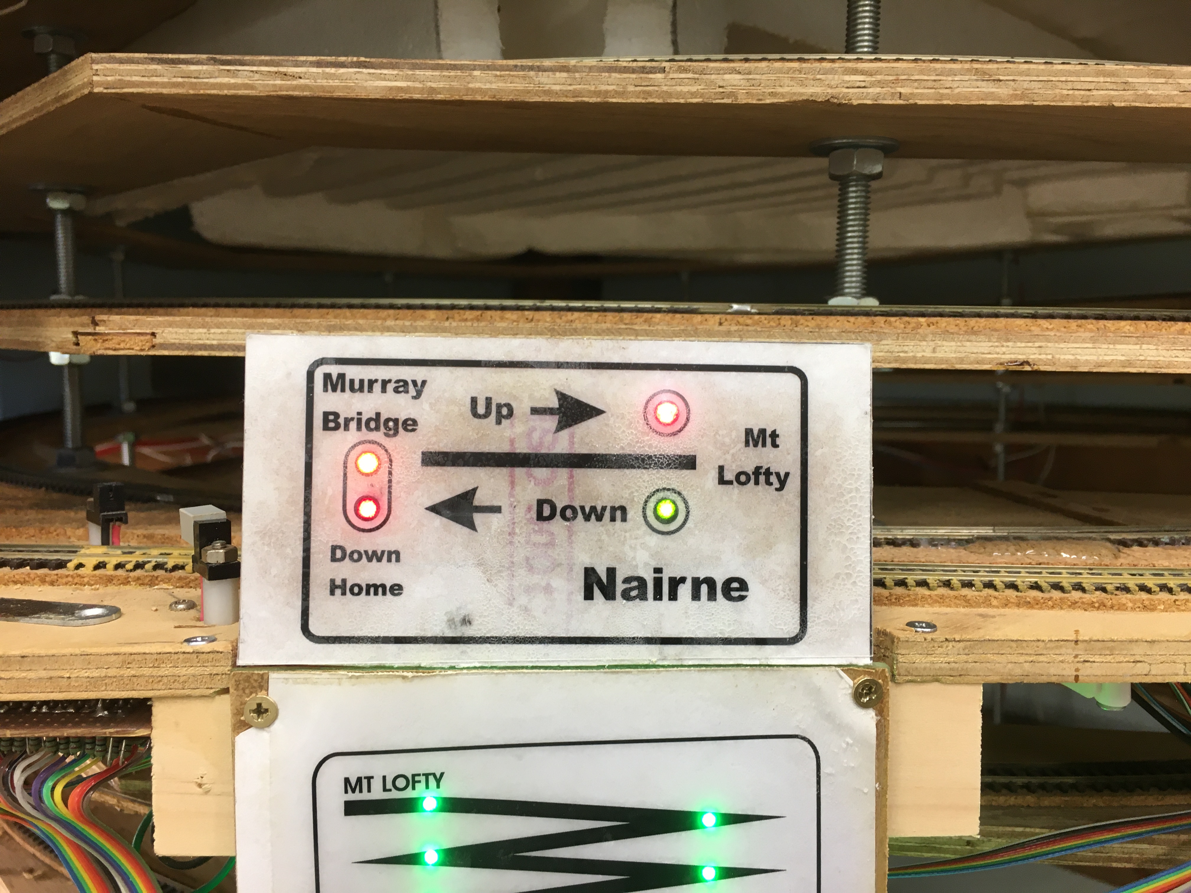
The Nairne repeater panel on the helix fascia, showing the Nairne Up and Down signals and the Murray Bridge Down Home.